Whether you’re building a rock crawler, a street truck, a drag car, or a lifted daily driver, getting the geometry right on your 4-link rear suspension is the difference between a vehicle that launches hard and rides well — and one that hops, squats, binds, or destroys U-joints. Our free 4-Link Suspension Geometry Calculator gives you instant center position, anti-squat percentage, pinion angle analysis, and individual link angles all in one tool.
Use the tabs below to calculate instant center and anti-squat from your link mount positions, analyze your pinion angle and U-joint cancellation, or calculate the angle of any individual link from its mount coordinates. All calculations use standard automotive suspension geometry formulas used by professional fabricators and engineers.
Table of Contents
- 4-Link Suspension Geometry Calculator (Free Tool)
- What Is a 4-Link Suspension?
- Instant Center Explained
- Anti-Squat Percentage Explained
- Pinion Angle and U-Joint Cancellation
- Link Angles and Their Effect on Geometry
- Parallel vs. Triangulated 4-Link
- Tuning Anti-Squat for Different Applications
- Frequently Asked Questions
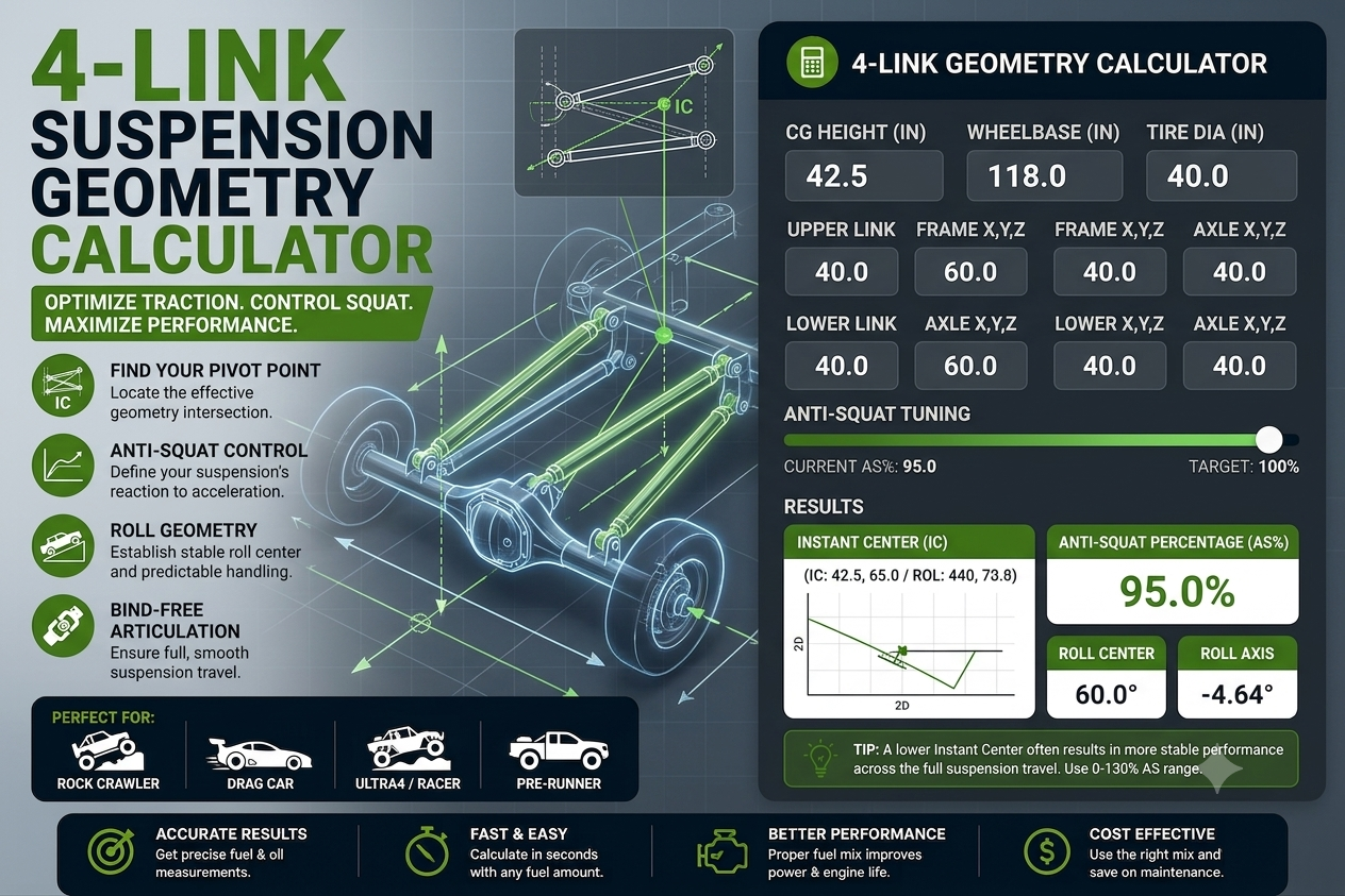
🔩 4-Link Suspension Geometry Calculator
Enter your link mount positions, wheelbase, and weight distribution below. All measurements are in inches from the rear axle centerline (horizontal) and inches from the ground (vertical). Positive horizontal = toward the front of the vehicle.
What Is a 4-Link Suspension?
A 4-link suspension (also called a 4-bar linkage or four-link) is a rear suspension design that uses four rigid links — two upper and two lower — to locate the rear axle housing relative to the vehicle chassis. Unlike leaf spring suspensions (which locate the axle both vertically and longitudinally through the spring itself) or 3-link designs, a 4-link completely separates the axle location function from the spring function. This gives the builder precise control over suspension geometry, anti-squat characteristics, pinion angle, and ride quality independently of the spring choice.
The four links are arranged in two pairs — one upper pair and one lower pair — running generally fore-and-aft between the axle housing and the chassis. In a parallel 4-link, both upper links run parallel to each other (as viewed from above), and both lower links run parallel. In a triangulated 4-link, the upper links are angled inward from the axle to a single central frame mount, eliminating the need for a Panhard bar to prevent lateral axle movement. The lower links in a triangulated design remain nearly parallel.
4-link suspensions are extremely popular in custom truck builds, off-road vehicles, hot rods, drag cars, and performance SUVs because they offer far more geometry tunability than leaf springs while being simpler to fabricate and understand than multi-link independent rear suspensions. Once you understand the key geometric principles — instant center, anti-squat, and pinion angle — you can tune a 4-link for virtually any application.
Instant Center Explained
The instant center (IC) is the single most important geometric concept in 4-link suspension design. It is the theoretical pivot point about which the rear axle appears to rotate at any given instant of suspension travel — and it determines nearly every performance characteristic of the suspension including anti-squat, anti-lift, and the rate at which these characteristics change through the suspension stroke.
In a 4-link suspension, the instant center is found geometrically by extending the lines of the upper and lower links — as viewed from the side — until they intersect. If you draw a straight line through the axle-end mount and the frame-end mount of the upper link, and do the same for the lower link, those two lines will cross at a specific point in space. That intersection is the instant center.
Instant Center Position and Its Effects
The position of the instant center — how far forward it is from the rear axle, and how high it is from the ground — directly controls the anti-squat percentage. In general:
- IC farther forward and higher up = more anti-squat percentage
- IC closer to the axle or lower down = less anti-squat percentage
- IC behind the axle (negative X) = the suspension actually promotes squat (negative anti-squat) — generally undesirable
- IC at infinity (parallel links) = the links produce no torque reaction, all load transfer comes through the springs — zero anti-squat
The IC moves as the suspension travels through its stroke — it is the instant center at a specific ride height. As the suspension compresses or extends, the IC location shifts, which is why anti-squat percentage is typically quoted at a specific ride height (usually static ride height). Understanding how the IC moves through suspension travel is an advanced topic that goes beyond basic geometry calculations and requires simulation software for precise analysis.
How the Calculator Finds the Instant Center
This calculator finds the instant center using standard coordinate geometry. With the rear axle centerline as the origin (x=0, y=0 at ground), the upper and lower link lines are defined by their mount coordinates. The calculator solves for the intersection of these two lines using the formula:
x_IC = (lower axle height − upper axle height) ÷ (upper slope − lower slope)
y_IC = upper slope × x_IC + upper axle height
Where slope = (frame mount height − axle mount height) ÷ horizontal distance between mounts.
Anti-Squat Percentage Explained
Anti-squat percentage describes how much the rear suspension geometry resists squatting under acceleration. When a rear-wheel-drive vehicle accelerates, the forward inertia of the vehicle’s weight transfers rearward — compressing the rear springs and extending the front springs. This weight transfer causes the familiar “squat” of the rear of the car under hard acceleration. The 4-link geometry can be designed to counteract this load transfer through the links themselves, reducing or eliminating spring compression.
- 0% anti-squat: The suspension geometry contributes nothing — all load transfer goes through the springs. Maximum squat under acceleration.
- 50% anti-squat: Half of the load transfer is handled by the links, half by the springs. Moderate squat.
- 100% anti-squat: The geometry theoretically handles all load transfer through the links, producing no spring compression (no squat). The chassis stays level under acceleration.
- 150%+ anti-squat: The geometry overcorrects — the rear of the vehicle actually rises under acceleration. This can cause wheel hop and is generally undesirable for street use.
The Anti-Squat Formula
Anti-squat percentage is calculated by drawing a line from the rear tire contact patch through the instant center. The height of this line where it passes through a vertical line at the vehicle’s center of gravity is compared to the CG height:
AS% = (Height of IC line at CG ÷ CG Height) × 100
Where: Height of IC line at CG = IC Height × (CG distance from rear ÷ IC distance from rear)
The CG distance from the rear axle depends on the vehicle’s weight distribution. For a vehicle with 52% of its weight on the rear axle, the CG is located at 48% of the wheelbase from the rear. Weight distribution affects the anti-squat calculation because it determines where the vertical CG reference line is positioned relative to the instant center.
Ideal Anti-Squat Percentages by Application
- Street/daily driver: 70–100% — Enough to minimize squat without causing excessive chassis jacking or wheel hop. The vehicle feels stable and planted under normal acceleration.
- Drag racing: 100–130% — Higher anti-squat plants the rear tires harder during launch. Some teams deliberately tune slightly over 100% to transfer additional load to the rear tires at launch, accepting minor jacking in exchange for better 60-foot times.
- Off-road/trail: 50–80% — Lower anti-squat allows the suspension to move more freely over terrain obstacles without chassis jacking interfering with wheel articulation.
- Rock crawling: 60–90% — Similar to trail use. Some builders prefer lower anti-squat in rock crawling configurations to allow the axle to move more independently from the chassis.
- Towing/hauling: 80–110% — Resistance to squat is valuable when towing, keeping the hitch height stable under load. Moderate to high anti-squat is generally beneficial.
Pinion Angle and U-Joint Cancellation
A Cardan (conventional) U-joint does not transmit rotation at a perfectly constant velocity — it produces a twice-per-revolution speed fluctuation (acceleration and deceleration) as the driveshaft rotates. At small angles, this fluctuation is negligible. At larger angles, it produces vibration. The solution is U-joint cancellation: by making the front and rear U-joint working angles equal and the joints phased 90° apart, the velocity fluctuation produced by the front joint is cancelled out by an equal-and-opposite fluctuation at the rear joint.
What Is Pinion Angle?
The pinion angle is the angle of the differential pinion shaft relative to horizontal. On most vehicles, the pinion points slightly upward toward the front of the vehicle (positive angle) when viewed from the side. The correct pinion angle in a 4-link build is not arbitrary — it must be set precisely to achieve U-joint cancellation with the transmission output angle and driveshaft angle.
The general rule: the transmission output shaft and the pinion shaft should be parallel to each other and both angled away from parallel with the driveshaft. If the transmission output drops 2° (nose down), the pinion should be set to 2° nose up so that both U-joints see the same working angle, canceling each other’s fluctuation.
U-Joint Working Angle Guidelines
- Under 1°: Ideal — nearly zero vibration or wear from joint angle
- 1°–3°: Good — acceptable for high-speed use with minimal vibration
- 3°–5°: Marginal — may cause vibration at highway speeds; U-joint life is reduced
- Over 5°: Poor — noticeable vibration and significantly shortened U-joint service life
- Over 7°–8°: Dangerous — risk of rapid U-joint failure and driveshaft damage
In a 4-link build, the pinion angle changes as the suspension travels — unlike leaf spring suspensions where the pinion angle is largely fixed. The pinion angle at static ride height should be set for correct U-joint angles at ride height, understanding that the angle will change under acceleration (squat), deceleration (dive), and during suspension cycling. This is another reason why anti-squat tuning and pinion angle tuning are closely related in 4-link design.
Link Angles and Their Effect on Geometry
The angle of each individual link — measured from horizontal — affects both the instant center location and the way the geometry changes through suspension travel. Understanding individual link angles helps you tune the suspension’s behavior and identify potential binding issues.
Upper Link Angle
The upper link typically runs at a steeper angle than the lower link — higher at the axle end, angled upward toward the frame. A steeper upper link angle (all else being equal) moves the instant center higher and forward, increasing anti-squat percentage. However, steep angles also increase bind risk if using rubber bushings and cause more pinion angle change through suspension travel.
A typical upper link angle for a street/performance truck is 4°–10° above horizontal. Off-road builds often run steeper upper links (8°–15°) to achieve adequate anti-squat with the long link lengths required for articulation.
Lower Link Angle
The lower link is usually longer than the upper link and runs at a shallower angle — often close to horizontal or slightly angled. A nearly horizontal lower link is advantageous because it minimizes the amount the lower link contributes to pinion angle change during suspension travel (the link moves in a flatter arc). However, some rise in the lower link is typically needed to help define the instant center above ground level.
A typical lower link angle for most applications is 1°–5° above horizontal. Very flat lower links combined with steeper upper links create a large divergence between the link lines, which moves the instant center closer to the axle — a configuration used in drag race builds to tune instant center position without changing link lengths.
Link Length and Its Role
Longer links produce less pinion angle change per inch of suspension travel, less bind through the suspension stroke, and better axle articulation. This is why off-road builds almost always use the longest links that physically fit the vehicle. Drag race builds sometimes use shorter, steeper links deliberately to tune instant center characteristics. For most street and trail applications, links of 36–52 inches (center-to-center) provide a good balance of geometry stability, ride quality, and articulation.
Parallel vs. Triangulated 4-Link
The two fundamental 4-link configurations each have significant advantages and tradeoffs:
Parallel 4-Link
In a parallel 4-link, both upper links run parallel to the vehicle centerline (or very nearly so), and both lower links run parallel. A Panhard bar or Watts link is required to prevent the axle from moving laterally — the four links themselves only control forward-rearward and vertical positioning.
- Advantages: Simpler geometry analysis, easier to tune anti-squat, equal binding characteristics on both sides, compatible with independent coilover and air spring setups
- Disadvantages: Requires a Panhard bar or Watts link for lateral location (adds cost and complexity), Panhard bar introduces slight lateral axle movement through suspension travel
- Best for: Drag racing, performance street trucks, serious build quality where geometry precision is prioritized
Triangulated 4-Link
In a triangulated 4-link, the upper links angle inward from wide-spaced axle mounts to a single central mount on the chassis (or two closely spaced mounts). This “V” or triangulated arrangement provides lateral axle location without a Panhard bar — the angled links resist sideways axle movement geometrically.
- Advantages: No Panhard bar required, simpler lateral location, more compact packaging in some applications, common OEM application (many factory leaf-spring-to-coilover conversions)
- Disadvantages: Introduces binding as the axle articulates (unequal link lengths as the axle rolls), lateral geometry changes through suspension travel, more complex to analyze and tune
- Best for: Off-road builds where packaging and simplicity matter, conversions from leaf springs, budget builds, vehicles where Panhard bar packaging is difficult
Tuning Anti-Squat for Different Applications
Once you understand what anti-squat percentage means and how it is affected by link geometry, you can tune it deliberately for your specific application. Here is a practical guide to adjusting anti-squat percentage using the mount positions in your 4-link:
To Increase Anti-Squat Percentage
- Raise the upper link frame mount: Moving the upper link’s chassis-end mount upward steepens the upper link angle, moving the IC higher and forward — increasing anti-squat.
- Lower the lower link frame mount: Moving the lower link’s frame-end mount downward increases link divergence (the angular difference between upper and lower links), which also moves the IC forward.
- Increase upper link angle relative to lower link: Any change that makes the two links point more toward each other (greater divergence) moves the IC closer to the axle and higher, increasing anti-squat.
- Use shorter upper links with the same mount heights: Shorter links have steeper angles from the same mount heights, moving the IC forward and up.
To Decrease Anti-Squat Percentage
- Lower the upper link frame mount: Flattening the upper link angle reduces its slope and moves the IC rearward and down.
- Raise the lower link frame mount: Bringing the lower link closer to parallel with the upper link reduces divergence and pushes the IC farther forward (or toward infinity for parallel links — zero anti-squat).
- Make the links more parallel: As the upper and lower link angles approach each other (parallel), the IC moves toward infinity and anti-squat approaches zero.
Adjustable Link Mounts
Many serious 4-link builders incorporate adjustable link mount positions — multiple bolt holes in a bracket that allow the frame or axle mount height to be changed without welding. This is particularly common in drag race applications where anti-squat percentage is tuned track-by-track based on track conditions, tire type, and shock absorber settings. For street and off-road use, fixed mounts are more common once the geometry is confirmed to work well for the application.
Frequently Asked Questions
What is the ideal anti-squat percentage for a street truck?
For a street-driven truck or SUV, most builders target 80–100% anti-squat at static ride height. This range minimizes body squat under acceleration for a planted, confident feel without causing chassis jacking or wheel hop. 100% is often considered the “sweet spot” for a vehicle that needs to be both planted under acceleration and comfortable over bumps at speed. Above 100% begins to compromise ride quality and can introduce wheel hop on rough surfaces.
How does ride height affect anti-squat percentage?
Changing ride height changes the geometric relationship between the mounts, altering the instant center position. A vehicle that has 100% anti-squat at stock ride height may have significantly different anti-squat after a suspension lift or drop. When calculating geometry for a lifted vehicle, always input the mount heights corresponding to the lifted ride height — not stock ride height dimensions. Most 4-link geometry calculators assume static ride height measurements.
Do I need a Panhard bar with a 4-link?
A parallel 4-link requires a Panhard bar (or Watts link) for lateral axle location — the four parallel links only prevent fore-aft and vertical axle movement, not side-to-side. A triangulated 4-link does not require a Panhard bar because the angled upper links provide lateral location geometrically. If you are unsure which type you have, look at the upper links from above: if they angle inward toward the center of the vehicle, you have a triangulated design. If they run straight forward, you have a parallel design that needs a Panhard bar.
What causes wheel hop in a 4-link suspension?
Wheel hop in a 4-link is typically caused by excessive anti-squat (over 120–130%) combined with soft or worn shock absorbers and stiff springs. When anti-squat is too high, the suspension tries to jack upward under acceleration rather than squatting — this reduces tire contact patch load, causing momentary wheel spin. The spinning wheel then “hops” as traction alternately breaks and regains. Solutions include reducing anti-squat percentage, increasing shock damping (especially rebound), reducing spring rate at the rear, or adding more rear tire contact patch through wider tires or lower tire pressure.